The Stoic Engine
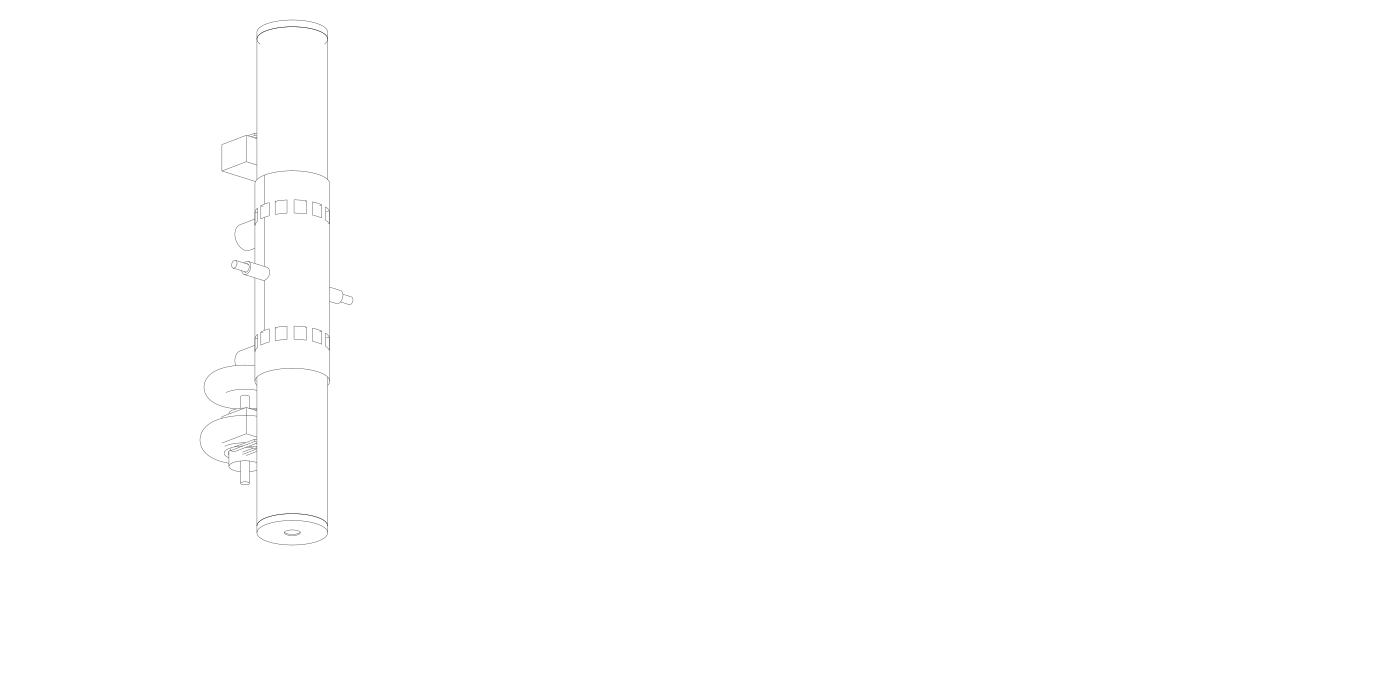
An opposed free-piston linear generator (FPLG). No crankshaft, no conrods, no gearbox, no valvetrain, no cylinder head. Two pistons fire against each other inside one cylinder and push a magnet straight through a coil. It never turns a wheel — it feeds a DC bus, and the vehicle runs on that.
Architecture
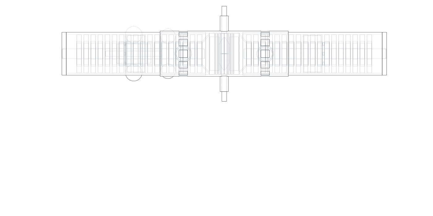
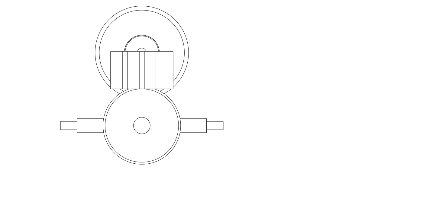
Combustion happens between the two piston crowns. Each piston carries a permanent-magnet tube that slides through a stator wound both inside and outside it — a dual-airgap linear alternator. A gas spring, not a crank, returns each piston. Nothing mechanical fixes top-dead-centre, so the compression ratio is a software variable.
The module, in motion
The same opposed free-piston module, animated — movers in matched opposition, combustion between the crowns, with live stroke, velocity and output readouts. Drag to orbit, scroll to zoom, toggle components.
Module variants
Power scales as the square of linear size (P ∝ k²); mass as the cube; frequency as 1/k — holding mean piston speed at 13 m/s. Bigger and slower always buys efficiency and life, and pays in mass.
| Parameter | TM-180 | TM-250 |
|---|---|---|
| Bore | 143 mm | 170 mm |
| Piston travel (each) | ±80.5 mm | ±96 mm |
| Swept volume | 5.17 L | 8.72 L |
| Cycle frequency (max) | 40.5 Hz | 34 Hz |
| Peak acceleration | 531 g | 446 g |
| Electrical output | 180 kW | 250 kW |
| Mechanical equivalent | 262 hp | 364 hp |
| Fuel at full output (full spec) | 36.3 L/h | 50.4 L/h |
| Overall length | 1,109 mm † | 1,840 mm |
| Mass | 212 kg † | 600 kg |
| Specific mass | 1.18 kg/kW † | 2.40 kg/kW |
| Cycles to 20,000 h | 2.9 billion | 2.4 billion |
2 × TM-180. Lighter for the same total power, redundant, fits a Ram 2500 rail gap side by side, and 143 mm bore is a more forgiving first scale to get the control system right.
2 × TM-250 = 500 kW continuous. The vehicle integration document's starting point for the hypercar power plant. Module count and battery size remain open.
Two sources disagreed on the TM-250's size. The lighter 1,322 mm / 360 kg pair (spec sheet, echoed in the GRIP doc) can't physically house two opposed 540 mm stators plus their gas springs — the stators alone are 1,080 mm. The 1,840 mm / 600 kg pair (engine handoff §3) fits that packing and matches the project's own car → truck → locomotive scaling ladder (length ∝ bore, mass ∝ bore³), so it is adopted here as the figure of record; 360 kg stands as an aggressive mass-optimised stretch target. † TM-180's package figures use the same light convention and likely need the same correction.
Where the efficiency comes from
Fuel-to-electricity at the DC bus, built up feature by feature. The baseline is defensible from published opposed-piston diesel results. The additions are individually demonstrated effects that have never been combined in one machine — a development ladder, not a spec.
| Step | Δ | Cumulative |
|---|---|---|
| Modern 4-stroke HD diesel (best point) | — | 42.0% |
| Opposed piston (no head) | +3.0 | 45.0% |
| Long stroke (high expansion) | +1.5 | 46.5% |
| Free piston (no crank/valvetrain) | +1.5 | 48.0% |
| Fixed-point operation | +0.5 | 48.5% |
| Linear alternator (95%) | −2.4 | 46.1% |
| Active rectifier (97%) | −1.4 | 44.7% |
| Scavenge blower parasitic | −1.8 | 42.9% |
| Addition | Δ | Cumulative |
|---|---|---|
| Baseline module | — | 42.9% |
| HCCI / lean premixed combustion | +2.5 | 45.4% |
| Software-variable compression ratio | +1.0 | 46.4% |
| Electric turbocompound (MGU-H) | +3.5 | 49.9% |
Further levers held in reserve — ORC bottoming cycle (+5–10), lower piston speed (+2–3), larger scale (+2–4) — put the combined ceiling near 55–58%, the territory of large marine two-strokes, reached by different means.
Load control
Throttling collapses efficiency at part load. Here, every cycle stays at optimal BMEP — only the rate changes. Efficiency versus frequency is a peak, not a slope: heat loss worsens as cycles slow, friction improves, and the two meet at a sweet spot.
The curve is asymmetric — from the design point up to max costs only 0.5 points; down to 12 Hz costs 4.5. When in doubt, run higher, not lower. Below the floor, pulse: run at 75 kW for a duty fraction and shut down between. Restart is nearly free.
| Frequency | Output | Efficiency | Dominant loss |
|---|---|---|---|
| 34 Hz | 256 kW | 46.0% | friction, gas exchange |
| 28 Hz | 211 kW | 46.5% | balanced — design point |
| 24 Hz | 180 kW | 46.0% | — |
| 17 Hz | 128 kW | 45.0% | heat loss rising |
| 12 Hz | 90 kW | 42.0% | heat loss |
| ~10 Hz | 75 kW | ~39.0% | floor |
One hardware set, every fuel
Software-variable compression ratio means a single engine runs diesel, LPG, methanol, ammonia or hydrogen — the primary commercial argument for the architecture.
| Fuel | Efficiency | MJ/L | Usable MJ/L | Notes |
|---|---|---|---|---|
| Diesel | 46% | 35.8 | 16.5 | Primary. Best usable density, right cetane for CI |
| LPG | 43–45% | 26.0 | 11.4 | RON ~110; needs spark assist or diesel pilot |
| Methanol | 48% | 15.8 | 7.6 | Best pure efficiency; half the range per litre |
| Ammonia | 43% | 12.7 | 5.5 | Zero-carbon option |
| Hydrogen @700 bar | 50% | 4.7 | 2.4 | Highest efficiency, worst density |
| Loop | Rate | Function |
|---|---|---|
| Position / collision | 10–20 kHz | No mechanical stop exists — piston-to-piston contact is catastrophic |
| Force / current | 10–20 kHz | Per-mover, local |
| Cycle allocation | ~1 kHz | Compression ratio, injection, frequency |
| Supervisor | ~100 Hz | Load demand → module on/off/frequency |
Mover position must be sensed to micron resolution. Symmetry is not mechanically enforced — control holds the two movers in matched opposition, or residual shaking force appears at the mounts. This is the "imbalance" problem that stalled single-mover designs.
| Component | Material | Reason |
|---|---|---|
| Piston crown | Forged Al-MMC | 160 W/m·K — not titanium, which would cook the crown |
| Mover web | Ti-6Al-4V | Structural; hot strength, low expansion |
| Liner | Compacted graphite iron | Graphite = solid lubricant; survives ring-over-port |
| Rings | Nitrided steel | Dissimilar to liner — never pair identical metals |
| Fatigue parts | Steel | Only steel has a true endurance limit |
| Magnets | Sm₂Co₁₇ | Stable to 350 °C; magnet temp is the binding constraint |
Open problems · build sequence